ZTexture
Applies an image as relief (displacement) on a mesh. The relief is created on the 3D mesh. You see the texture before generating the relief, and you can adjust its position, scale and height.
Toolbar button: 
When to use
When you want to engrave a texture (leather, grain, pattern) on a 3D part. At the end you get a new mesh with real relief, ready to use or export.
Before you start
- Auto mode: the 3D mesh must carry the link to its flat pair, saved by
ZUnwrapPlusorZUnroll. You only select the 3D mesh. - Manual mode: select pairs of 3D mesh + flattened 2D mesh of the same part. The 2D mesh must be the flattened version of the 3D one.
- It does not work with surfaces, polysurfaces, curves, or a mesh without a 2D pair.
Steps
- Run
ZTexture. - At the prompt
Select all meshes automatically or select 3D/2D mesh pairs manually, choose Auto or Manual.- Auto: when prompted
Select all meshes made from ZUnwrapPlus:, select the 3D meshes (several at once) and press Enter. - Manual: repeat for each pair:
Pair #1 - Select 3D mesh, thenPair #1 - Select mesh 2D (unwraped 3D mesh), thenSelect one more pair?(Yes / No).
- Auto: when prompted
- The command line shows
N pair(s) selected. Opening the window.... Each pair gets a numbered dot (1, 2, 3…) on the 3D and on the 2D mesh. - In the window, click Select texture folder and choose the image in the thumbnail grid.
- Adjust the parameters (see Window options).
- Click Apply displacement to create the relief. The command line shows
Displacement applied to N mesh(es): … vertices in total. - Click Delete displacement to remove the relief, or End displacement to close the window.
Window options
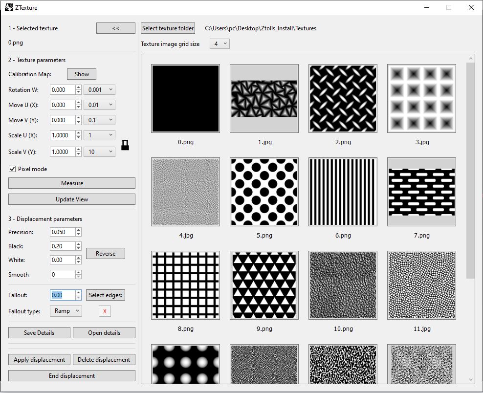
Thumbnail panel (right side)
| Field / button | What it does | Values | Default |
|---|---|---|---|
| Select texture folder | Chooses the folder of images. The thumbnails appear below. | folder | last used |
| Texture image grid size | Size of the thumbnails. | 1 to 4 | 3 |
1 - Selected texture
Shows the name of the image you chose. The << / >> button hides / shows the thumbnail panel.
2 - Texture parameters
| Field / button | What it does | Values | Default |
|---|---|---|---|
| Calibration Map: Show / Hide | Show displays a calibration image with neutral values and yellow direction arrows. Hide restores your values. | n/a | n/a |
| Rotation W | Rotates the texture. | −360 to 360 (degrees) | 0 |
| Move U (X), Move V (Y) | Moves the texture. | −100000 to 100000 (mm) | 0 |
| Scale U (X), Scale V (Y) | Scale of the texture. | 0.001 to 100000 | 1 |
| Lock | Turns the synchronization of Scale U and V on or off. | on / off | on |
| List next to each field | Step of the field arrow. | 0.001 to 100 (scale: 0.0001 to 100) | n/a |
| Pixel mode | Scales by pixel of the image. | checkbox | off |
| Measure | Selects the mesh and takes measurements on the texture. | n/a | n/a |
| Update View | If necessary, updates the view with the current parameters. | n/a | n/a |
3 - Displacement parameters
| Field / button | What it does | Values | Default |
|---|---|---|---|
| Precision | Distance between points of the relief. Smaller gives more detail and a heavier mesh. | 0.01 to 10 (mm) | 2 |
| Black / White | Height of black and of white. | −10 to 10 (mm) | 0 / 5 |
| Reverse | Swaps Black and White. | n/a | n/a |
| Smooth | Smooths the image only for the calculation (1 = 0.1 mm). It does not change the texture you see. | 0 to 50 (whole numbers); 0 = off | 0 |
| Fallout | Distance over which the relief goes down to zero near the edge. See Fallout. | 0 to 100 (mm); 0 = off | 0 |
| Fallout type | Shape of the descent. | Ramp, Arc, BiArc | Ramp |
| Select edges: | Sets a different Fallout for each edge of the boundary. See Fallout per edge. | n/a | n/a |
| X | Resets Select edges: of one mesh. | n/a | n/a |
Other buttons
| Button | What it does |
|---|---|
| Save Details / Open details | Saves / loads all the parameters in a file. |
| Apply displacement | Creates the relief. |
| Delete displacement | Deletes the last relief generated. |
| End displacement | Closes the window. |
Values are remembered between sessions. With a single mesh, the parameters of the last application on that mesh are restored.
Fallout
Fallout is the distance, from the edge of the mesh, over which the relief goes down to zero. Fallout type sets the shape of that descent:
| Ramp | Arc | BiArc |
|---|---|---|
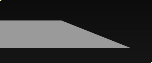 |
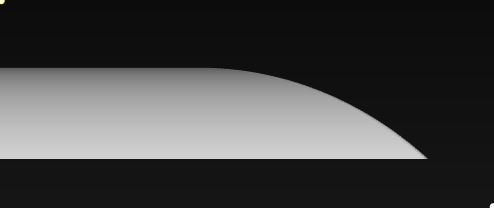 |
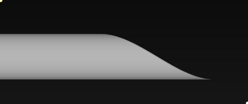 |
| Straight descent. | Rounded descent. | Smooth S-shaped descent. |
Fallout per edge
Use Select edges: to set a different Fallout for each edge of the boundary. Each edge is shown in a different color, with a label. The label shows N/A until the edge is configured.
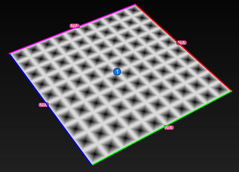
- Click Select edges:.
- When prompted
Select edge curve(s) to configure…, select the edge(s). - Answer
Fallout distance for this edge (mm)andFallout type for this edge.
With several meshes, the button shows Select edges:3/5 and goes through the meshes one by one. Enter or Esc moves to the next one, keeping what you have already set. Finish ends.
The red X resets Select edges: of one mesh. With several meshes it asks Select the mesh (or its edge dots) to reset, or choose All. Enter and Esc cancel.
Result
- One new mesh per pair, named
Displaced_Mesh_01,_02…, on the layerDisplaced_Mesh(created if it does not exist, steel blue). - The original 3D mesh is kept, with the texture displayed.
- The 2D mesh is moved to the layer
Unwrapped_Objects::Part_XXand turns pink. The numbered dots stay in the document. - Rhino shows a warning once: tick Save textures when saving (File > Save). Without it, the image is not stored inside the
.3dmfile.
Tips
- Start with a coarse Precision (a larger value, for example 0.2 mm) to see the result. Lower it only for the final version.
- A low Precision produces many vertices. A value between 0.03 and 0.05 is recommended for general use. Performance depends on your computer.
- A Fallout smaller than Precision is ignored (it is the same as 0).
Related command
ZExportTextureDetails saves the details file (JSON) of a textured mesh, without opening this window.